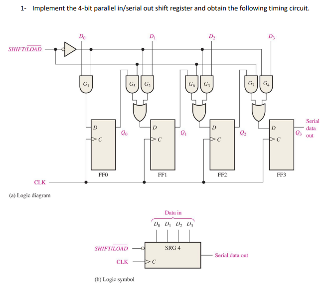


Do take a look at the format of an accepted file before contributing. Edit the testbench in the file testbench.v by instantiating the module you want to check, and providing the stimulus in the initial block.įeel free to submit pull requests with more such modules.cd into the repository - cd getting-started-with-verilog/.Clone this repository to local machine - git clone.In addition to the CLK Signal, Clear (CLR) signal is also connected. one bit at a time through a single data line and produces a parallel output.Fig.3 shows a SIPO mode consisting of 4 D-Type Flip-Flop’s (FF 0, FF 1, FF 2 and FF3). This time I am show that and made a important part of circuit. The SIPO mode of Shift Registers accepts data serially i.e. Now using logisim software made a circuit.How to use that software and made circuit. Typical Example of circuit with datapath and control unit 2 Schematic of Serial In Serial Out (SISO) Mode.N Bit Shift Register (universal shift register).32 Bit LFSR - Pseudo Random Number Generator.It is best suited for those who are just getting started with Verilog. An n-bit shift register can be formed by connecting n flip-flops where each flip flop stores a single bit of data. The bits stored in such registers can be made to move within the registers and in/out of the registers by applying clock pulses. The following circuit is a four-bit Serial in – parallel out shift register constructed by D flip-flops.This repository contains some verilog modules which are the elementary and fundamental building blocks of a digital circuit. Shift Register is a group of flip flops used to store multiple bits of data. VHDL code for Parallel In Parallel Out Shift Register library ieee Įnd arch Serial In – Parallel Out Shift Registersįor Serial in – parallel out shift registers, all data bits appear on the parallel outputs following the data bits enters sequentially through each flipflop. Once the register is clocked, all the data at the D inputs appear at the corresponding Q outputs simultaneously. The D’s are the parallel inputs and the Q’s are the parallel outputs. The following circuit is a four-bit parallel in – parallel out shift register constructed by D flip-flops. Parallel In – Parallel Out Shift Registersįor parallel in – parallel out shift registers, all data bits appear on the parallel outputs immediately following the simultaneous entry of the data bits. VHDL Code for shift register can be categorised in serial in serial out shift register, serial in parallel out shift register, parallel in parallel out shift register and parallel in serial out shift register. VHDL Code for Serial In Parallel Out Shift Register.

Serial In – Parallel Out Shift Registers.VHDL code for Parallel In Parallel Out Shift Register.Parallel In – Parallel Out Shift Registers.


 0 kommentar(er)
